Designing Parts for CNC Machining: Chapter 1
Nov 21, 2020
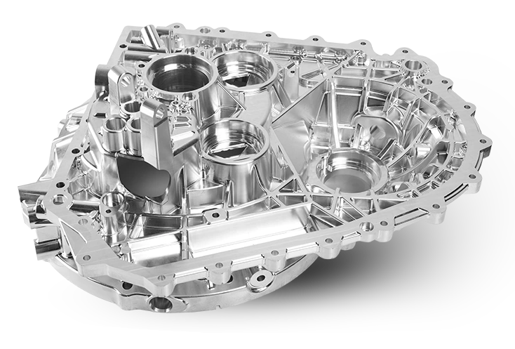
Table of Contents
- Introduction……………….…………1
- Design Restrictions………….…2
- Interior Fillets……………….………3
- Deep Cavities and Pockets….4
- Outside Corners……………………5
- Threaded Holes……………………6
- Drilled Holes………………….……..7
- Surface Flatness…………………..8
- Mating Parts………………….……..9
- Wall Thickness……………………10
- Undercuts…………………….……..11
Introduction
The machining of parts on any CNC machine begins with a design that utilizes the best practices to make the process both feasible and cost-effective. What makes this challenging is the lack of industry-wide standards to help designers.
This chapter focuses on the best design practices for today’s CNC machines. Much of it comes from manufacturing experts and CNC machine shops that have accumulated both programming and practical machining experience.
CNC machining is a technology in which material is removed (subtractive manufacturing) instead of the additive method that 3-D printing employs. It must adhere to specific rules and guidelines that designers must consider as they develop a CAD (computer-aided design) model.
Sometimes it is feasible to machine a part on the CNC but not necessarily cost-effective. We will point that out in those cases. In job shops where one-off pieces are standard, these slower operations will have minimal effect on costs. However, during high-volume production runs, they can be cost-prohibitive.
CNC machines are notable for accuracy and repeatability. They can hold close tolerances for both prototyping and production parts. The chapter begins with a few design restrictions and continues with design rules for CNC machining.
Design Restrictions
Although there is flexibility in designing CNC parts, there are specific restrictions that designers cannot ignore. These limitations are connected to the mechanics of the cutting process and generally involve tool access and geometry.
Tool access
Keep in mind that in most cases, a cutting tool must move toward the workpiece directly from above it. The exception would be with multi-axis CNCs, which allow the tool to “ramp” toward the workpiece. But if you cannot access any portion of the part from above, it isn’t possible to machine it on the CNC. The only exception is undercutting, which we will touch on later.
Another tool access issue is part features with a considerable depth to width ratio. For example, reaching the bottom of a deep cavity requires extra-long cutters, which can flex and vibrate, resulting in less accurate dimensions.
A rule of thumb for designers is to create parts that allow machining with the largest diameter and the shortest length.
Tool geometry
The two most common CNC cutting tools — end mills and drills—are cylindrically shaped and have a limited cutting length. The geometry of the tool determines the radii on the part. For instance, the inside corners of the part will always have a radius, so there can be no sharp inside corners from a CNC.
Now, let’s look at the possible values to which designers should adhere:
Interior Fillets
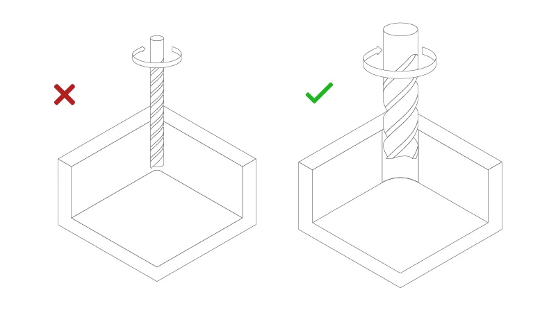
Vertical internal corner radii should be 1/3 of the cavity depth or larger. This value ensures that you will be using an end mill with a diameter that aligns with the guidelines for cavity depth.
One other suggestion is to design the corner radius to be slightly larger than the radius of the end mill. Doing this will allow the smaller tool to machine a circular path while creating the radius. This method is preferable to having a tool path in which the end mill travels straight into the corner before taking a 90-degree angle, which can create chatter and a lower-quality finish.
Since end mills typically are flat or have a small radius on their bottom cutting edge, the cavity floor (where the bottom of the cavity meets the sidewall) will have little or no radius. If a substantial floor radius is needed, use a ball end mill.
Deep Cavities and Pockets
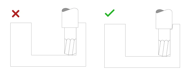
As mentioned, end mills have a limited efficient cutting length, which should be restricted to about 3 to 4 times their diameter. Anything deeper than that will raise the possibilities of tool deflection, chip removal issues, and vibrations. If possible, design parts with multiple cavity depths that make it possible to use a shorter end mill when deep cavities or pockets are required.
Outside Corners
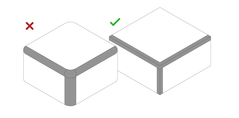
When designing outside corners, a chamfer is preferable to a radius. An outside radius requires a special form cutter and an accurate setup, or surface machining with a ball end mill. Adding the radius using either of these methods is time-consuming and adds extra costs to the part.
Threaded Holes
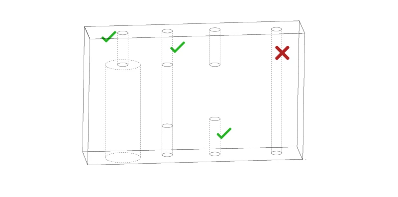
Tapped holes are the most common threaded hole. Tap into a through-hole whenever possible. If you must use a blind hole, the drill should be 1.5 times the threads’ depth. Choosing the largest thread size possible will aid machining and minimize the chance of tap breakage. Thread the part only as deep as necessary to hold down costs.
Drilled Holes
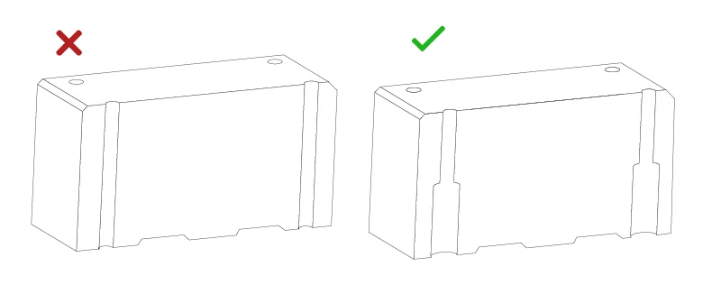
You can use either a drill bit or an end mill to add holes to a part. The size of the drill bit should be a standard diameter either in metric or imperial units. Holes that require tighter tolerances can be finished with a reamer.
The maximum recommended drilling depth is usually four times the diameter, although that can be increased by using extended length-length drill bits that are either made of cobalt or solid carbide. (Experienced shops, such as RapidDirect, can explain your options).
Holes with non-standard diameters require an end mill, and the maximum depth restrictions will apply. Deeper holes are machined with special drill bits. You can drill blind holes with either a drill bit or an end mill. Keep in mind that the bottom of drilled holes will have a conical floor, while end mills will leave it with a flat bottom.
Surface Flatness
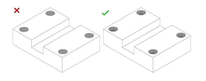
For machined surfaces with a high degree of flatness, ad bosses to the surface. The bosses indicate which areas need to be flatness controlled. They also simplify painting and other finishing operations.
Mating Parts
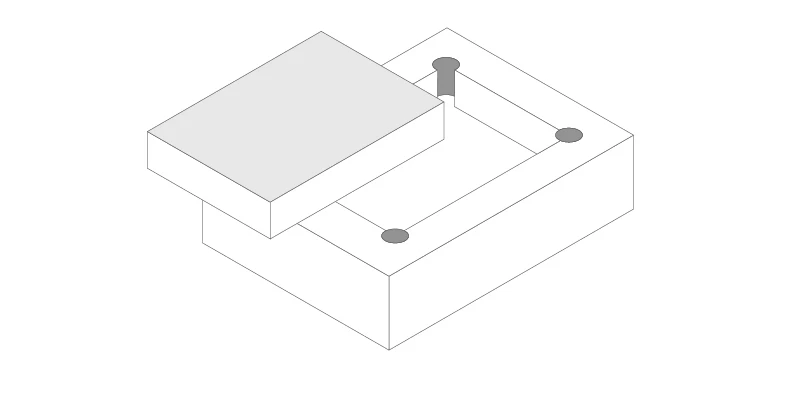
When designing parts that must fit into each other, ensure the inside corner diameter of the cavity is slightly smaller than the outside diameter of the part to be inserted. Another option is to provide clearance in the cavity corners by plunging an end mill or drill. Design at least 2.5mm clearance between parts if you are allowing +/-.125mm as a tolerance.
Wall Thickness
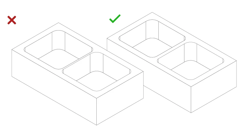
Wall thicknesses that fall below 1mm are difficult to machine and easy to break. Thin walls significantly reduce the stiffness of the material, increasing vibration during machining and affecting accuracy. Plastics are even more susceptible to warping from the residual stresses and softening from the increased temperature, so minimum wall thicknesses in plastic should be larger than in metal. Thin walls tend to ramp up the costs of a part.
Undercuts
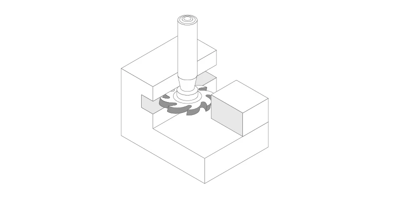
Since undercut areas are not accessible from above, they cannot be machined with standard cutting tools. As a result, you will need to use either a t-slot or dovetail cutter, either of which offers a slow, time-consuming operation. Avoid undercuts, if at all possible. If unavoidable, keep the undercut amount to a minimum.