Sheet Metal Fabrication Design Guide
Apr 22, 2019
An in-depth guide to help you optimize your part design for sheet metal fabrication.
- Introduction
- What is Sheet Metal Fabrication
- Material Selection
- Design Limitations for Sheet Metal
- Surface Finishes
- Quick Tips for Sheet Metal Fabrication
Introduction
Before sheet metal parts can produced on the shop floor, a viable design that meets the manufacturing process’ tolerances and capabilities is needed.
By acknowledging and adhering to the limitations of sheet metal fabrication in the design stage, the risk of challenges arising at the manufacturing stage is reduced, resulting in a more time and cost efficient manufacturing process.
We’ve put together a comprehensive design guide for sheet metal fabrication that will help our customers make the most out of our manufacturing services for a range of metal products. Our Sheet Metal Fabrication Design Guide will cover the fundamentals of Sheet Metal Fabrication, including the various tools used in the process; what materials we offer and how to choose the best metal for your project; design limitations for the process; available surface finishes and more.
At China Medical CNC Machining Inc., we want our services to fit your needs and that involves keeping production as seamless and efficient as possible to deliver your metal prototypes and finished products.
What is Sheet Metal Fabrication
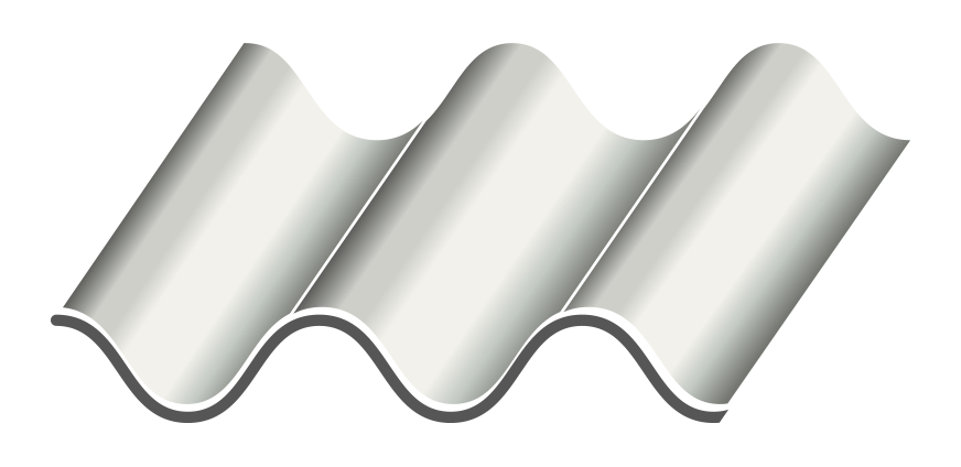
Sheet metal fabrication is a common manufacturing process in which thin, flat pieces of metal are formed into structures using a range of techniques, including punching, stamping, cutting and bending.
The various processes involved in sheet metal fabrication provide versatility, allowing for a broad range of parts and products to be produced. This, in combination with the malleable nature of sheet metals, means that the design possibilities for sheet metal fabrication are vast.
Some of the most common application areas for sheet metal components are in the automotive, aerospace, medical and architectural sectors. Sheet metal parts are known for their precision, durability and resistance—properties which are crucial for end-use applications in the aforementioned industries.
Like most other manufacturing processes today, sheet metal fabrication begins with a 3D CAD model. When all the design specifications are met and the 3D model is verified, the CAD file is converted into machine code which instructs the punching, stamping, cutting or bending tools on how to manipulate the raw material. The part can then be finished using a range of surface finishing treatments.
Before diving into the design limitations and tips for sheet metal fabrication, here is a brief overview of the various techniques involved in the process:
Punching
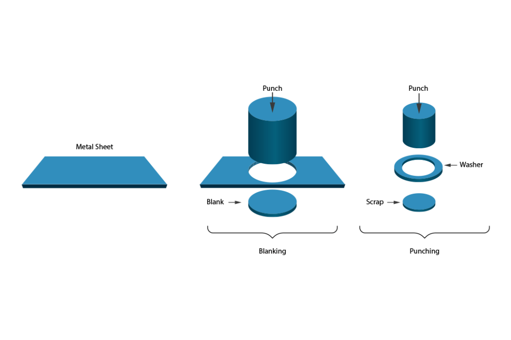
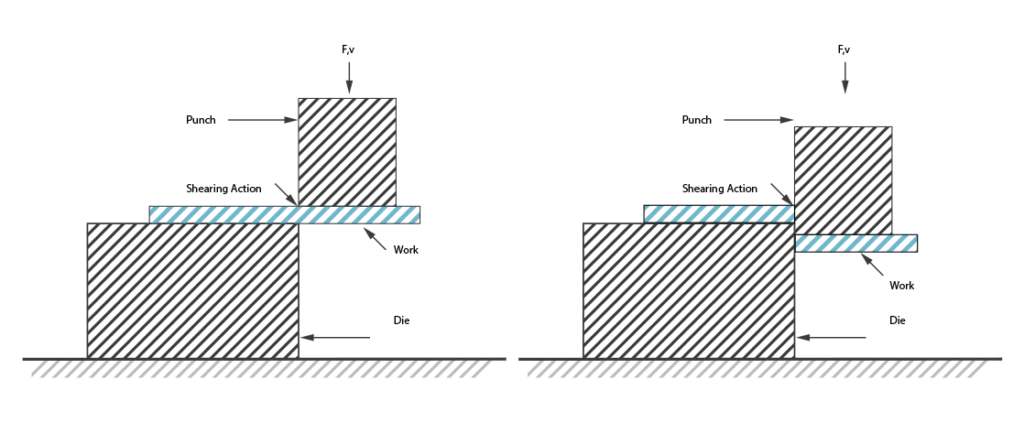
The punching process consists of fitting a sheet of metal in between a punch and a die, which are mounted inside a press. Both the punch and die have the same shape, though they vary incrementally in size so that when the punch is pressed into the die, a hole or depression is created in the sheet metal.
Cutting
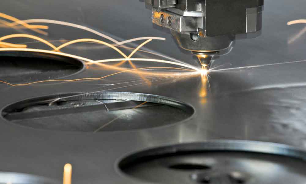
In sheet metal fabrication, many types of tools are used to cut sheet metal to size. For softer metals, it is even possible to use manual tin snips, though more sophisticated cutting tools such as high-velocity water jets, lasers and plasma cutting tools are more common for industrial manufacturing.
Stamping
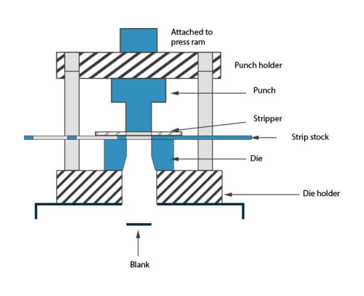
In the stamping process, a piece of sheet metal stock is placed into a stamping press which forms the metal into the desired net shape using male and female dies.
Bending

As the name implies, bending is a manufacturing process in which metal sheets are bent using brakes or presses. The most common types of bends are V-shaped, U-shaped and channel-shaped forms.
Material Selection
In terms of materials, sheet metal fabrication is limited by what types of metals are manufactured as sheet stock. The most common materials for the process are steel (especially Stainless steel), Aluminum and Copper. At China Medical CNC Machining Inc., we offer a range of grades for each material:
Steel
- Stainless Steel 301
- Stainless Steel 316/316L
- Stainless Steel 304
- Steel 1018
Aluminum
- Aluminum 5052
Copper
- Copper 101
- Copper C110
- Copper 260 (Brass)
When choosing what material to work with for a given part, it is important to consider the properties of each sheet metal type. Stainless steel, for instance, offers excellent corrosion-resistance and good weldability. Aluminum, for its part, is easy to form as a sheet metal because of its ductility. It is also one of the most cost effective metals to work with. Copper—including its brass alloy—is a popular sheet metal because of its corrosion resistance and conductivity.
In addition to metal type, sheet metal stock is also distinguished by gauge—or the thickness of the metal. Sheet metal thicknesses usually vary between 0.006 and 0.25 inches (0.15 and 6.35 mm). Gauge numbers do not represent the thickness measurement, however. They generally range from 3 to 38, with the highest gauge number corresponding to the thinnest piece of sheet metal.
Design Limitations for Sheet Metal Fabrication
Sheet metal fabrication is a versatile manufacturing approach for producing a broad range of metal parts. Like all production processes, the technology comes with advantages and disadvantages. By knowing the process’ limitations and tolerances, however, it is possible to design products that maximize sheet metal fabrication.
Material Thickness
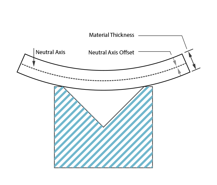
When designing a part for sheet metal fabrication, it is crucial to ensure that the part’s wall thickness is consistent throughout its geometry. This is because parts are fabricated from a piece of sheet metal, which is bent, cut or stamped into shape.
Bend Radius
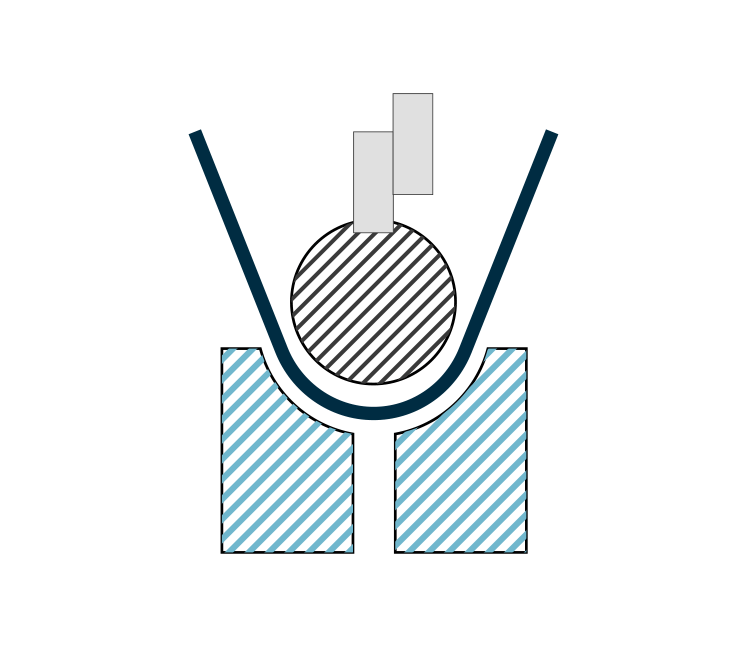
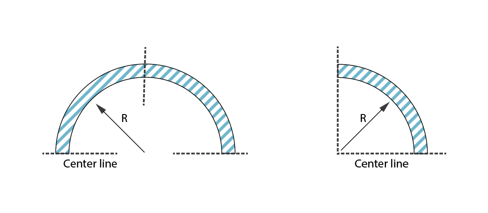
Where possible, it is helpful to make sure that all bends are designed to follow the same direction so that the part does not have to be reoriented during production. Further, by maintaining the same bend radius across a part’s design, production costs can be kept down. When designing a part with bends, it is also useful to maintain an inside bend radius that is at least equivalent in size to the sheet metal thickness.
Curls
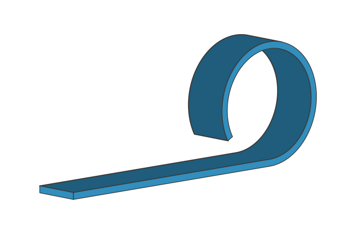
In sheet metal fabrication, curls are used to make safe, rounded edges for parts. When integrating curls into a design, it is important to make sure that the outside radius of the curl is at least double the sheet metal thickness and that any holes in the part’s design are placed at a certain distance from the curl (at least the distance of the curl radius + the sheet thickness).
Hems

Like curls, hems are integrated into sheet metal parts to make the edges of parts safe for handling. There are a number of hem types, including open, flat and tear-dropped hems. Unlike curls, which have no raw edge, hems to still have exposed edges. For open hems, the inside diameter should be at least as large as the material thickness, while the length of the hem should be at least four times the metal’s thickness. For tear-drop hems, the same measurements apply as well as an opening at least a quarter of the thickness.
Countersinks
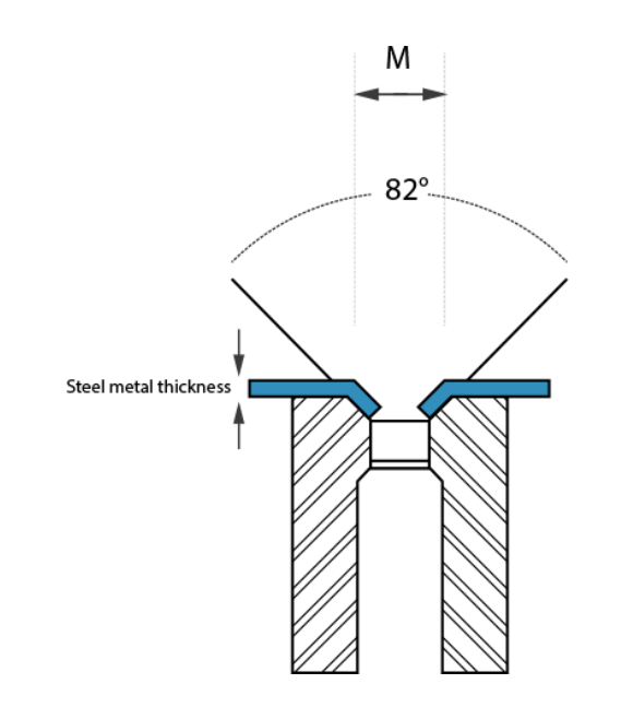
When integrating countersinks into a part design, a number of factors should be taken into consideration, including angle of the opening, diameter of the hole and placement of multiple countersinks. Though less precise than CNC machining, punch tools are effective and more affordable for producing countersinks. To keep costs reduced, it is also helpful to maintain standard countersink dimensions. In terms of dimensions, countersinks can be up to 0.6 times the sheet metal thickness and should be placed at least eight times the material thickness from each other. It is also worth noting that countersinks should be at least 4x the metal’s thickness from an edge and three times the thickness from a bend.
Holes
In sheet metal fabrication, holes are commonly used for parts that require mounting or wiring. Fabricating the holes can be done either using a drill or punching tool—the latter of which is more cost efficient, though results in a slight taper at the bottom of the hole. When designing parts with holes, the hole diameters should be at least as large as the material thickness. To ensure that holes are not deformed, they should be placed at a certain distance from bends (at least 2.5x the metal thickness + the bend radius). Punched holes should also be placed at least 2x the sheet’s thickness away from edges to avoid deformed edges.
Notches and bend relief
Notching is usually used in sheet metal fabrication to facilitate bends or part assembly. The process uses a punch press to remove material from the outer edge of the metal stock. Bend reliefs, for their part, are useful to ensure that a bend transitioning into a flat surface does not tear or break at their intersection. Bend reliefs should be at least as deep as the radius of the bend and at least as wide as the material thickness.
Sheet Metal Surface Finishes
After metal sheets have been formed into the desired shape, there are a number of optional finishing processes that can be used to improve or modify the surface quality of the part. Surface finishing treatments can not only alter the aesthetic finish of metal components, but they can also change the part’s properties, offering more wear-resistance, better conductivity and more.
Bead Blast
This finishing treatment consists of blowing small glass beads against the surface of the sheet metal part in a controlled manner. This technique results in a smooth surface with a matte texture. In bead blasting, various materials—such as sand, garnet, walnut shells and metal beads—are used to clean parts or prepare them for subsequent surface treatments.
Powder Coat
In the powder coating process, powdered paint is sprayed directly onto the part, which is then baked in an oven, forming a durable, wear-resistant and corrosion-resistant layer. A wide variety of colour options are available in the powder coating process.
Anodization (Type II or Type III)
Anodization provides excellent corrosion resistance to sheet metal parts, improving the hardness and wear-resistance of the surface while dissipating heat. Anodization is the most common surface treatment for painting and priming as it provides a high quality surface finish. China Medical CNC Machining Inc. offers two types of anodization: Type II, which is corrosion resistant; and Type III which is thicker and adds a wear-resistant layer. Both anodization processes allow for a broad range of color finishes.
Chemical Film (Chromate Conversion Coating)
Chemical films are corrosion resistant and provide good conductivity. The coating process results in a golden surface finish and is predominantly used as a base for paint.
Custom
China Medical CNC Machining Inc. customers can also choose a customized finishing process based on their requirements. Our experts will work with clients to achieve specific finishing requests, such as surface cleaning, enhanced shine, stripping, corrosion resistance, tarnish resistance and vulcanization.
Quick Tips to Maximize your Sheet Metal Fabrication
Stay consistent
Maintaining the same bend radii, countersink and hole diameters across a part’s design will reduce the need for multiple tool changes, resulting in a faster and cheaper production process.
Don’t forget reliefs
Bend reliefs are an integral feature that help to ensure that a part meets its design intent without the risk of tearing or breaking. The simple design features should be integrated wherever a bend transitions into a flat surface.
Ensure clearances
In the design process, it is important to make sure that design features such as holes, countersinks and notches are not integrated too close to any bends or edges. Failure to meet these clearances can result in hole deformations and bulging edges.
Check your corners
Though it is possible to leave sheet metal parts with sharp edges, it is more cost effective to design parts with corner fillets. These fillets should measure about half of the sheet metal’s thickness.
Provide a flat layout
If possible, provide a flat layout of your part’s design to allow for better production planning. A flat layout is essentially what the finished part will look like before it is bent into shape. This layout will include cuts, notches, holes, etc. and will enable the manufacturer to better estimate costs and plan out production.